
Home / Our Products / NLW1 Air Circuit Breaker
Product Catalog
NLW1Air Circuit Breaker
NLW1 series intelligent circuit breaker for power distribution networks with AC 50/60Hz, rated operating voltages of 400V and 690V, and rated current of 200A to 6300A. It meets IEC60947-2.
Call 01001539094 or 01012235710, or message us on WhatsApp.
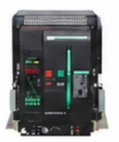
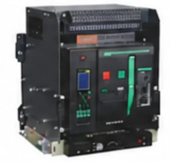
- Rated current
- 200–6300A
- Frame sizes
- 5models
- Pole number
- 3P, 4P
- Icu at AC 400V (6300 A frame)
- up to 120kA
- Standard
- IEC60947-2
NLW1 Series
Application
NLW1 series intelligent circuit breaker is mainly suitable for a power distribution network with AC 50/60Hz, rated operating voltages of 400V, 690V, and rated current of 200A to 6300Adistribute power, protect circuit and power devices against overload, under voltage, short circuit, and ground faults. The core part of the circuit breaker adopts intelligent controller with precise selective protection, which can avoid unnecessary power failure so as to improve the reliability, continuity and safety of the power supply system.
The circuit breaker can be widely used in the power distribution system of power stations, factories, mines and modern commercial buildings, especially in intelligent buildings. It is also often used in wind power generation, solar power generation and other green energy filed The circuit breaker meets the IEC60947-2.
Type
- Installation mode
- stationary type drawer type
- Operation mode
- electric operation, manual operation
- Category use
- type B
- Pole number
- 3, 4
- Type of release device
- intelligent controllers, under voltage release trigger and shunt release trigger.
Intelligent type controller function
a. With overload long delay reverse time limit, short delay reverse time limit, short delay fixed time limit , instantaneous action and other protection functions, can be set by the user, composed of the required protection characteristics:
- b. Ground fault protection function;
- c. Overload alarm function;
- d. Test function;
- e. Overload alarm function;
- f. Self-diagnostic function;
- h. MCR function;
- i. Thermal simulation function;
- j. Contact loss indication;
Storage Environment
- The minimum temperature shall not be lower than-25°C, and the maximum temperature shall not exceed + 55°C;
- The relative temperature (+ 25°C) shall not exceed 95%;
- Products in the process of transportation,should be handled with specialcare,should not be inverted, should be tried to avoid violent collision.
Working Environment
- The ambient air temperature is-5°C ~ + 50°C, and the average value of 24h does not exceed + 35°C (except for special orders).
- The altitude of the installation site shall not exceed 2,000 m.
- The relative humidity of the air at the installation site shall not exceed 50% when the maximum temperature is +50°C. It can have higher relative humidity at lower temperature. The mean minimum temperature of the wettest month shall not exceed +25°C, and the mean maximum relative humidity of the month shall not exceed 90%, taking into account the condensation occurring on the surface of the product due to temperature changes.
- The pollution grade is Grade 3.
- The main circuit of circuit breaker, the under voltage tripping coil and the primary coil of power transformer are installed as IV, while the other auxiliary circuit and control circuit are installed as III.
- The installation position shall be vertical,and the inclination ineach direction shall not exceed 5.
What is inside
NLW1 Air circuit breaker
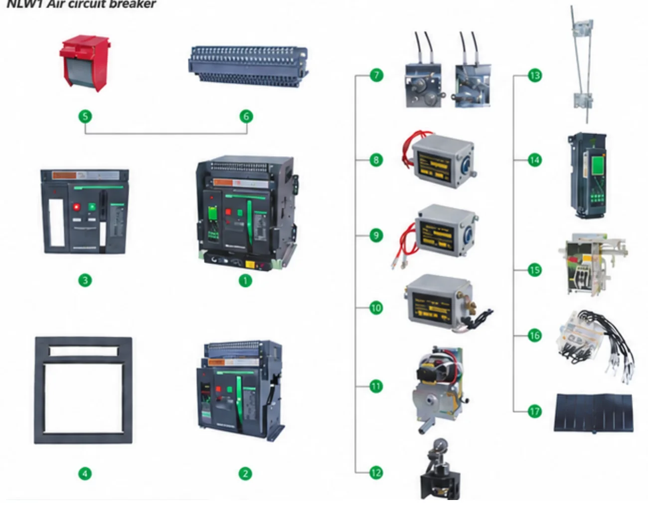
- Drawer circuit breaker
- Stationary circuit breaker
- Front panel
- Door frame
- Arc chamber
- Secondary circuit
- Steel cable interlock
- Closing electromagnet
- Shunt release
- Under voltage release
- Electro drive energy storage mechanism
- Lock
- Lever interlock
- Intelligent controller
- Operating mechanism
- Auxiliary switch
- Phase partition
Ratings by frame size
Technical Parameters
Quick selection
| Model | Rated current In (A) | Icu at AC 400V (kA) | Icu at AC 690V (kA) |
|---|---|---|---|
| NLW1-1600 | 200, 400, 630, 800, 1000, 1250, 1600 | 65 | 50 |
| NLW1-2000 | 400, 630, 800, 1000, 1250, 1600, 2000 | 80 | 50 |
| NLW1-3200 | 2000, 2500, 2900, 3200, 4000 (increase capacity type) | 100 | 65 |
| NLW1-4000 | 3600, 4000 | 100 | 65 |
| NLW1-6300 | 4000, 5000, 6300 | 120 | – |
Summary of the full parameter table below. A dash (–) means the catalogue gives no value.
Swipe the table sideways to see all models.
Technical parameter of circuit breaker (see Table 1)
| Model | NLW1-1600 | NLW1-2000 | NLW1-3200 | NLW1-4000 | NLW1-6300 | |
|---|---|---|---|---|---|---|
| Rated current In (A) | 200,400,630 800,1000 1250,1600 | 400,630,800 1000,1250 1600,2000 | 2000,2500 2900,3200,4000 (Increase capacity type) | 3600, 4000 | 4000,5000 6300 | |
| Neutral pole current rating In (A) | 100%In | 100%In | 100%In | 50%In | 50%In | |
| Rated operating voltage Ue (V) | AC400/690/800 | |||||
| Pole number | 3P, 4P | |||||
| Rated impact withstand voltage Uimp (kV) | AC12 | |||||
| Nominal insulation voltage Ui (V) | AC1000 | |||||
| Power frequency withstand voltage (V) | AC3500 | |||||
| Rated limit short circuit breaking capacity Icu(kA) | AC 400V | 65 | 80 | 100 | 100 | 120 |
| AC 690V | 50 | 50 | 65 | 65 | - | |
| Rated short circuit breaking capacity Ics (kA) | AC 400V | 55 | 65 | 80 | 80 | 100 |
| AC 690V | 50 | 50 | 65 | 65 | - | |
| Rated short time withstand current Icw/ 1s (kA) | AC 400V | 55 | 50 | 65 | 65 | 100 |
| AC 690V | 50 | 50 | 65 | 65 | - | |
| Category of use | B | |||||
| Full break time (no additional delay) | ≤30ms | |||||
| Closing time | ≤70ms | |||||
| Electrical life (times)≤3200 1h/20 >3200 1h/10 | AC 400V | 6000 | 5000 | 3000 | 2000 | 1500 |
| AC 690V | 5000 | 4000 | 2000 | 1500 | 1000 | |
| Mechanical life (times)≤2500 1h/20 >2500 1h/10 | Maintenance-free | 15000 | 10000 | 8000 | 5000 | 2000 |
| Have maintenance | 20000 | 12000 | 10000 | 6000 | 2500 | |
| Mechanical life of the drawer holder (1h/20times) | 1000 | 1000 | 1000 | 600 | 300 | |
| Into the line way | Up or down incoming line | |||||
| Arc distance(mm) | 0 | |||||
| Installation mode | Stationary type or Drawer type | |||||
| Mode of connection | Horizontal wiring or vertical wiring | Horizontal wiring | ||||
Note: One time of mechanical life of the drawer base refers to when the circuit breaker body is shaken from → "separated" to → "connected" and then to the → "separated" position in the drawer base.
Maximum power loss of circuit breaker incoming and outgoing line (ambient temperature + 50°C)
| Model | Frame current Inm (A) | Power loss(W) | |||
|---|---|---|---|---|---|
| 3P Drawer type | 4P Drawer type | 3P Stationa type | 4P Stationa type | ||
| NLW1- 1600 | 1600 | 230 | 306 | 136 | 182 |
| NLW1-2000 | 2000 | 395 | 526 | 262 | 350 |
| NLW1- 3200 | 3200 | 556 | 742 | 307 | 409 |
| NLW1-4000 | 4000 | 660 | 880 | 332 | 450 |
| NLW1-6300 | 6300 | 1429 | 1905 | - | - |
Note: Power consumption of the circuit breaker refers to the power consumption of the main circuit measured by the circuit breaker with the rated current at room temperature, excluding the power of other power loss accessories of the circuit breaker. This table data is only for reference and cannot be used as power consumption in actual use of thecircuit breaker.
Altitude reduction coefficient
When the altitude exceeds 2000 meters, the insulation performance, cooling performance and pressure in the atmosphere will change, and its performance can be corrected by referring to Table 4.
| Altitude (m) | 2000 | 3000 | 4000 | 5000 |
|---|---|---|---|---|
| Working current Ie | 1 | 0.93 | 0.88 | 0.82 |
| Short circuit breaking capacity Icu, Ics | 1 | 0.83 | 0.71 | 0.63 |
| Short circuit tolerance Icw | 1 | 0.83 | 0.71 | 0.63 |
| Rated impact withstand voltage Uimp | 1 | 0.9 | 0.71 | 0.63 |
| Power frequency withstand voltage | 1 | 0.9 | 0.71 | 0.63 |
| Rated insulation voltage Ui | 1 | 0.83 | 0.71 | 0.63 |
The recommendation for installing of busbar
| Rated current (A) | External copper busbar (width*thickness) mm | Required busbar qty per pole | Cross-sectional area (mm²) |
|---|---|---|---|
| 200 | 20×5 | 1 | 100 |
| 400 | 40×5 | 1 | 200 |
| 630 | 40×5 | 2 | 400 |
| 800 | 50×5 | 2 | 500 |
| 1000 | 60×5 | 2 | 600 |
| 1250 | 80×5 | 2 | 800 |
| 1600 | 100×5 | 2 | 1000 |
| 2000 | 100×5 | 3 | 1500 |
| 2500 | 100×5 | 4 | 2000 |
| 2900 | 100×10 | 3 | 3000 |
| 3200 | 100×10 | 4 | 4000 |
| 3600 | 100×10 | 5 | 5000 |
| 4000 | 100×10 | 5 | 5000 |
| 5000 | 100×10 | 6 | 6000 |
| 6300 | 100×10 | 8 | 8000 |
Note:
- The specification in the table is that the circuit breaker used in ambient environment of 50°C and installed open.
- The material of busbar is T2 bare copper. The specification of the external copper busbar can be changed according to the actual use situation, but it should meet the cross-sectional area requirements corresponding to different currents in the table.
Intelligent controller
Protection Performance
a. Protection performance of the intelligent controller
The over current protection characteristic curve of the intelligent controller is shown in Figure 1.
The setting range I / In and accuracy of the intelligent controller:
Swipe the table sideways to see all columns.
| Protection type | Long time delay | Short time delay | Instantaneous | Ground protection | ||||
|---|---|---|---|---|---|---|---|---|
| Frame grade | IR | Accuracy | Isd | Accuracy | Ii | Accuracy | Ig | Accuracy |
| NLW1-1600 | (0.4~1)In | ±10% | (0.4~15)In | ±10% | 1In~50kA +OFF | ±15% | (0.2~1)In | ±10% |
| NLW1-2000 | 1In~50kA +OFF | |||||||
| NLW1-3200/4000 | 1In~75kA +OFF | |||||||
| NLW1-6300 | 1In~100kA +OFF | |||||||
b. Long time delay over current protection reverse time limit action characteristics
For the long time delay over current protection, the reverse time limit curve conforms to the characteristic curve of I²TL = (1.5 Ir)² tL. Where I is the actual action current; TL is the actual action time with a long time delay; and tL is the setting time for a long time delay of 1.5 IR.
Swipe the table sideways to see all columns.
| Current multiple | Action time | ||||||
|---|---|---|---|---|---|---|---|
| 1.05IR | No action within 2 h | ||||||
| 1.3IR | <1h action | ||||||
| 1.5IR | Setting time(s) | 15 | 30 | 60 | 120 | 240 | 480 |
| 2.0IR | Actuation time(s) | 8.4 | 16.9 | 33.7 | 67.5 | 135 | 270 |
c. Short time delay over current protection action characteristics
Swipe the table sideways to see all columns.
| Current | Action time | |||||
|---|---|---|---|---|---|---|
| I≥Isd, I≤8IR | Inverse time limit | I² Ts = (8IR)² ts | ||||
| I≥Isd, I>8IR | Fixed time limit | Setting time (s) | 0.1 | 0.2 | 0.3 | 0.4 |
| Action time(s) | 0.06 | 0.14 | 0.23 | 0.35 | ||
Note: a) action time tolerance ± 15%. b) I is the actual action current; ts is the set time for short time delay; and Ts is the actual action time.
d. Short circuit instantaneous protection action characteristics
The instantaneous protection function prevents the load from short circuit in the distribution system. This kind of fault usually happens between phases so the short circuit current is relatively big, which needs to be disconnected quickly.
This protection is executed based on the true effective value of the current. When I≤0.85Ii, I> 1.15 Ii (I is actual short circuit current).
e. The protection characteristics and curve of grounding fault (Figure 2)
There are two kinds of ground fault protection: one is to detect the current of neutral point, when the current of three-phase is in balance, the neutral point current is zero. When the current of three-phase is in imbalance, the current of neutral point exceeds the set value, the intelligent controller alarms, the circuit breaker is disconnected or constantly open according to the instruction after the fixed delay time. The other is to detect the current of the grounding wire, when the current exceeds the set value, the intelligent controller alarms, make the circuit breaker be disconnected or constantly open according to the instruction after the fixed delay time. The grounding fault protection characteristics is fixed time limit.
| Action current Set 6Point Ig | (0.2~1)In+OFF |
|---|---|
| Action characteristic | ≤0.8Ig failure to actuate |
| ≥1.1Ig deferred action | |
| Setting time (s) | (0.2~1)In+OFF (OFF That only the alarm is not removed) |
f. Self-diagnostic function
The intelligent controller can diagnose its own fault when failure happens to the computer. It can display "E" (means error) or alarm, and restart computer at the same time. The circuit breaker can be disconnected when necessary.
When the local ambient temperature reaches 80°C or the temperature in the casing exceeds 80°C due to the heat of the contact, an alarm can be issued, and the circuit breaker can be switched off at a smaller current (when the user needs).
g. Load monitoring function
Set two set values Ic1 and Ic2, setting range of both are (0.2~1) In. The delay feature of Ic1 is the reverse time limit characteristic, Its delay setting value is 1 / 2 of the long delay setting value. There are two kinds of delay characteristics for Ic2: one is the reverse time limit characteristics, its value of time setting is 1/ 4 of the long delay setting value; The other is the fixed time limit characteristic, Its delay time is 60s. The first delay function is used to switch off the last important load when the current approaches the set overload value. The latter delay function is used to delay switching off unimportant load to decrease the current in order to maintain the power supply for main circuit and important load circuits when the current exceeds the Ic1 value. When the current drops to Ic2, a command is issued after a delay to reconnect the lower circuit that has been cut off restore the power supply to the entire system. The load monitoring features are shown in the following figure.
h. Display function of the controller
The controller can display the operating current and voltage (i. e., ammeter and voltmeter function) during operation.
When the fault occurs, it displays the section specified by its protection characteristics, and latch the fault display and fault current after disconnecting the circuit. During setting, it displays current, time and section type of the section. If it is a delay action, the indicator light will flash during the action.
The indicator light will change from flashing to constant lighting after the circuit breaker is disconnected. During the test, the test current, delay time, test indication and test action section are displayed.
i. DO signal and alarm function
The controller can output 8 DO output signals for the controller or sound and light alarm indication.The corresponding functions include: overload pre-alarm signal, short circuit tripping signal (short delay and instantaneous), long delay tripping signal, ground tripping or alarm signal, load monitoring 1 signal, load monitoring 2 signal, self-diagnosis alarm signal and fault tripping signal (OCR).
j. MCR and over ultimate trip protection
The MCR and over ultimate trip function is high speed instantaneous protection. The fault current signal sends action command directly through the hardware comparison circuit. MCR protection only works at the moment of switch-on of the circuit breaker (about 100ms), while the over ultimate trip protection always plays a role during operation. MCR protection is to protect the ultimate switching capacity of the circuit breaker to prevent the power grid from being in the short circuit fault state before the switch is switched on. While switching on the circuit breaker, the current generated in the moment will be bigger than the switching capacity, the controller switches off the circuit breaker in an instantaneous manner. Over ultimate trip protection is to protect the ultimate load capacity of the circuit breaker, and prevent the circuit breaker from being damaged by the current exceeding the ultimate load capacity.
k. Thermal memory fuction
Due to overload or short delay tripping, there will be thermal effect which is similar to bimetal in the controller. The overload thermal effect energy is released in 30min while the short delay energy is released in 15min. During this period, if overload or short delay failure occurs again, the disconnection time will become shorter. The controller loses power and eliminates the energy automatically.
Preset value of the intelligent controller
Swipe the table sideways to see all columns.
| Controller type | Long delay | Short delay | Instantaneous | Ground protection | Load monitoring | ||||
|---|---|---|---|---|---|---|---|---|---|
| IR | tL | Isd | tL | Ii | Ig | tG | Ic1 | Ic2 | |
| NLW1-M | 1In | 60s | 8I R | 0.2s | 12I R | 0.8I R | OFF | 1In | |
| NLW1-2H/3H | 1In | 60s | 8I R | 0.2s | 12I R | 0.8I R | OFF | 1In | |
Stationary and drawer type
Structure Overview
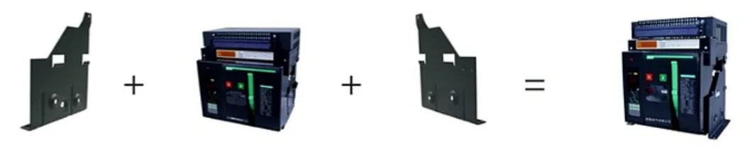
Stationary type circuit breaker is mainly composed of the contact system, intelligent controller, manual operation mechanism, electric operation mechanism and fixed installation board.
Drawer type circuit breaker is mainly composed of the contact system, intelligent controller, manual operation mechanism, electric operation mechanism and drawer holder.
The contact system is closed in the insulating floor and each phase contact is separated by an insulation board to form a small chamber, while the intelligent controller, the manual operation mechanism and the electric operation mechanism are arranged in front of it, forming independent units. If one of the units is broken, the whole unit can be removed and replaced with a new one. The circuit breaker consists of a body and a fixed bracket, and becomes a stationary type.
Drawer Type Circuit Breaker
The drawer type circuit breaker is composed of the circuit breaker body and the drawer holder. The guide rail in the drawer holder can be pulled in and out, and the main loop is connected through the bus on the circuit breaker body and the bridge plug on the drawer holder.
The drawer type circuit breaker has three working positions: “connected”, “test” and “separated”. The position is changed by rotating the handle in or out, and the three positions are indicated by the pointer on the drawer seat beam.
- Connected: the main loop and the secondary loop are connected.
- Test: the main loop is disconnected and separated by an insulation partition; only the secondary loop is connected, so some necessary action tests can be carried out.
- Separated: the main loop and the secondary loop are all disconnected.
The drawer type circuit breaker also has a mechanical interlocking device: it can only be switched on in the “connected” or “test” position, and cannot be switched on in the middle position between “connected” and “test”.
There are two types of circuit breakers: drawer type and fixed type
The circuit breaker consists of two parts: the body and the drawer holder, and the body is inserted into the drawer holder.
Intelligent controller mechanical reset button
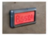
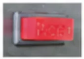
Operating state of the operating mechanism
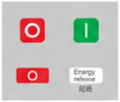
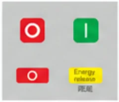
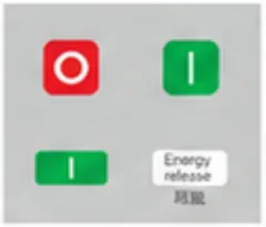
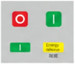
Drawer type circuit breaker (Only the Drawer type circuit breakers have this function)
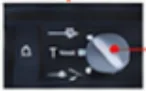 “Connected” position Main circuit and second circuit are connected
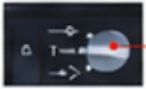 “Test” position: main circuit is disconnected and second circuit is connected
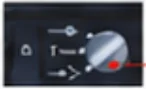 “Separated” position: Main circuit and seconda
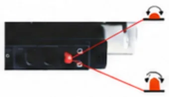
- After the position is locked, operate the shake handle, press the position lock button to release the lock (unlock state)
- In the separated state, the connected three positions: the main board is locked, and the shake handle cannot operate (lock state)
There position lock of the drawer holder: lock the circuit breaker body in the drawer holder: "separated", "test" and "connected".
Secondary circuit
Control Loop
Secondary loop wiring diagram of NLW1-1600~6300 with M-type intelligent controller
Secondary-circuit wiring diagram of NLW1-1600~6300 with H-type intelligent controller
The red dotted line in the wiring diagram is wired by the user himself, and the control circuit should be protected by the fuse.
Note: Under voltage release can also be connected frequently closed butt emergency cases.
| Symbol | Paraphrase | Remarks |
|---|---|---|
| Q | Under voltage release | Optional attachment |
| F | Shunt release | |
| X | Closing electromagnet | |
| DF | Auxiliary switch | |
| SA | Motor micro-dynamic switch | |
| M | Electric motor | |
| XT | Terminal connector | User self-provided |
| ⊗ | Signal lamp | User self-provided |
| SB1 | Manual switch button | User self-provided |
| SB2 | Manual closing button |
Swipe the table sideways to read the full description.
| Terminal number | Terminal function description | Remarks |
|---|---|---|
| 1,2 | Auxiliary power supply input: AC230V, AC400V, DC220V, and DC110V | Type M default configuration 2H / 3H communication type configuration |
| 3,4,5 | Fault trip contact output (4 # is the public end), contact capacity: AC250V, 3A | |
| 6,7 | Breaker state auxiliary contact output (often open), contact capacity: AC250V, 3A | |
| 8,9 | Breaker state auxiliary contact output (often open), contact capacity: AC250V, 3A | |
| 20 | Protection area (PE) | |
| 10,11 | Rs485 communication interf ace lead, 10 to A, 11 to B (default Modbus) | 2H / 3H communication type configuration |
| 12,19 | Relay contact output: 12 and 13 are DO 1; 14 and 15 are DO 2; 16,17 D 3 for remote switch DO contacts; 18 and 19 DO 4 for remote switch contacts | |
| 21,22,23,24 | Voltage measurement input: 21 N, 22 A, 23 B, 24 C | |
| 25,26 | a: Connect neutral wire transformer for 3P + N; b: Connect leakage transformer for leakage protection (alternative) | Optional attachment |
| 27,28 | Under voltage release (Direct connected to autonomous loop power supply to improve the reliability and security of power supply) | Optional attachment |
| 29,30 | Shunt release | |
| 31,32 | Closing electromagnet | |
| 33,34,35 | Electric motor(35 can be directly connected to the power supply automatic pre-storage, or can connect the power supply manual pre-storage) | |
| 36~47 | Auxiliary switch Terminal terminal (default four ad conversion) |
NLW1-2000~6300 Auxiliary swich (DF) type
Outline and mounting size (mm)
Overall Dimension
Choose a frame size, then tap a drawing to enlarge it.
NLW1-1600 Fixed Circuit breaker Outline and mounting size (mm)
NLW1-1600 drawer type circuit breaker profile with installation size (mm)
NLW1-2000 Fixed Circuit breaker Outline and mounting size (mm)
NLW1-2000 drawer type circuit breaker profile with installation size (mm)
NLW1-3200 Fixed Circuit breaker Outline and mounting size (mm)
NLW1-3200 drawer type circuit breaker profile with installation size (mm)
NLW1-4000 / 3P Fixed Circuit breaker Outline and mounting size (mm)
NLW1-4000 / 3P expansion drawer type circuit breaker profile with installation size (mm)
NLW1-6300 Fixed Circuit breaker Outline and mounting size (mm)
NLW1-6300 drawer type circuit breaker profile with installation size (mm)
Panel, buttons and settings
Intelligent Controller
The description of panel display and function of the controller
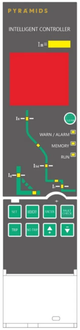
| Information on the panel | Function declaration |
|---|---|
| In | Rated current of the controller |
| G | Current of ground or N phase ( constant light refer to ground, ash refer to N phase) |
| L1 | Current of phase A |
| L2 | Current of phase B |
| L3 | Current of phase C |
| MAX | Maximum phase current |
| A | Unit of current |
| kA | Unit of current |
| S | Unit of time (s) |
| test | Simulated tripping test |
| Ic1 | Load monitoring No. 1 |
| Ic2 | Load monitoring No. 2 |
| δ | Current imbalance protection |
| Ig | Ground protection |
| IR | Long time delay protection |
| Isd | Short time delay protection |
| Ii | Instantaneous protection |
| WARN / ALARM | Fault alarm |
| MEMORY | Save information |
| RUN | In normal operation state |
| Button Function declaration | |
|---|---|
| CLEAN | Clear the fault display on screen and return to the run state |
| SET | Press the button, then click the button continuously to display all of parameters in sequence |
| MEMORY | Conrm to save when the parameters are set |
| FUNCTION | Auxiliary function |
| FAULT CHECK | Check the fault record |
| TRIP | Simulate tripping test |
| NO TRIP | Simulated non-tripping test |
| ▲ + | Adjust the set parameter value to be increased |
| ▼ − | Adjust the set parameter value to be decreased |
How to set the parameters of the intelligent controller
Use those four buttons on the controller panel: SET , ▲ + , ▼ − , MEMORY to set all the parameters of the controller.
The basic steps are described as follows:
- ① Click the button of " SET " continuously to check all of parameters in sequence periodically. When a parameter is checked, the original set value of the parameter is displayed on the screen, and the corresponding indicator on the panel will be light on. If you do not need to change this parameter, go on clicking the butt on of " SET ".
- ② If you need to change the original set parameter, click the button of " ▲ + "or" ▼ − " continuously. In the process of setting for current, in order to get the required set value quickly, the user can click the button of "function" to converse the mode of adjustment between fast adjustment code and fine adjustment code until the required value is achieved.
- ③ Press button of " MEMORY " to save the new set parameters. If no other parameters are required to be set, follow the step mentioned in ④ to exit the set. Otherwise, continue according to the step mentioned in ① .
- ④ Press the button of " CLEAN " to exit the setting state.
All the protection parameters of the controller should be set according to Ir1 <Ir 2 <Ir 3 strictly.
Simulation test operation of the controller
Simulation characteristics test against grounded, long delay, short delay and nstantaneous can be oper ated for the controller. Two kinds of test are available: tripping and non-tripping. The first one needs to break the circuit breaker, the second one does not break the circuit breaker. If faults such as overload or short circuit occurs during the test, the system will automatically terminate the test state and turn to the fault processing state.
Get the full NLW1 catalog
Download the PDF catalog, or send us your rated current, pole number and installation mode and our team will prepare a quotation.
Call us on 01001539094 or 01012235710, or message us on WhatsApp.