
Home / Our Products / NLM1E Electronic MCCB
Product Catalog
NLM1EElectronic Molded Case Circuit Breaker
NLM1E series electronic molded case circuit breaker for AC 50 Hz networks with rated voltages of 400V and 690V and rated current up to 1250A. Small volume, high breaking capacity, short arcing distance and anti-vibration.
Call 01001539094 or 01012235710, or message us on WhatsApp.
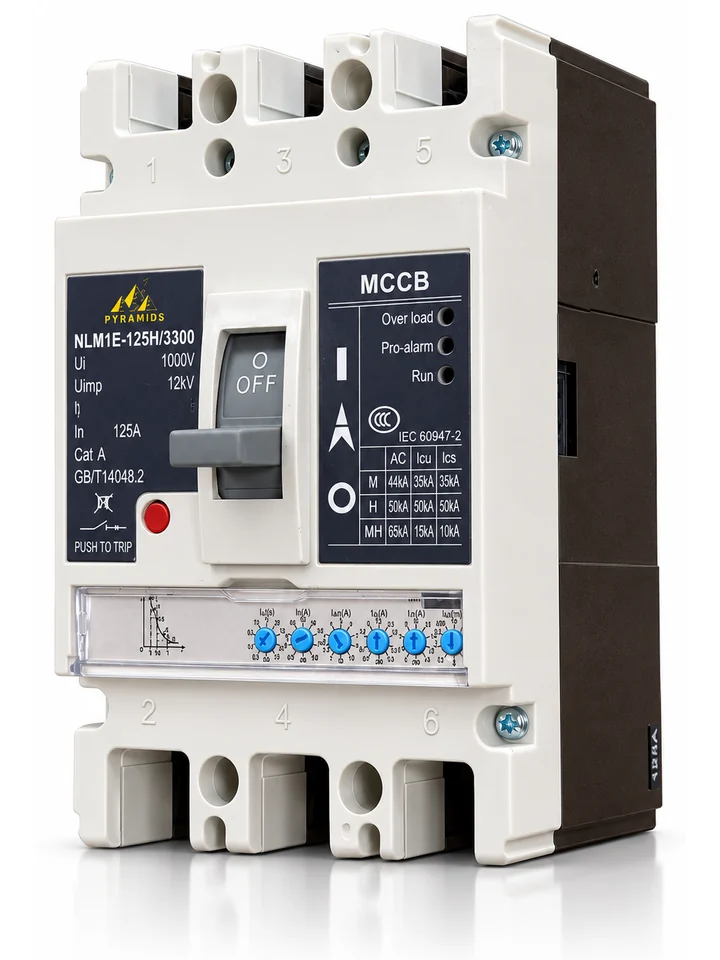
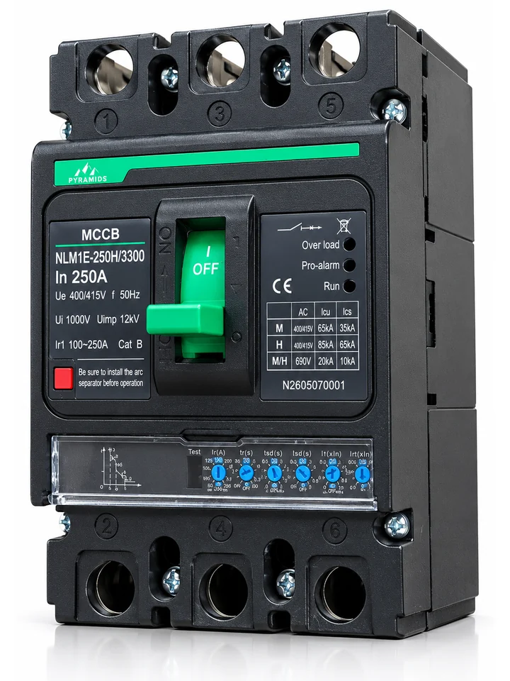
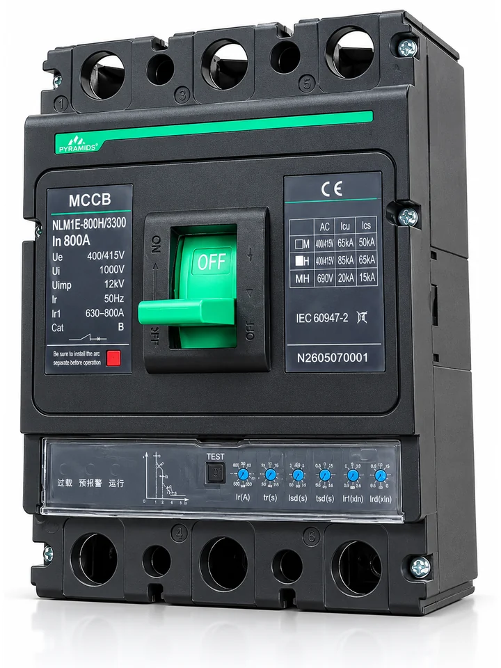
- Rated current
- up to 1250A
- Frame sizes
- 5models
- Pole number
- 3P, 4P
- Icu (highest class)
- up to 85kA
- Standards
- IEC 60947, GB/T 14048
NLM1E Series
Application
NLM1E series electronic Moulded case circuit breaker is a new designed MCCB developed and manufactured by adopting international advanced technology. Its rated insulation voltage is 800V, is applied to the circuit of AC 50HZ, rated working voltage 400V/690, rated current up to 1250A as infrequently switch and starting of motor. MCCB has the functions of overload long delay inverse time limit, short-circuit short delay inverse time limit, short-circuit short delay definite time limit, short-circuit instantaneous and under-voltage protection, to protect the circuit and power equipment against damage.
MCCB has the characteristics of small volume, high breaking capacity, short arcing distance, and anti-vibration.
MCCB has the isolation function.
Type
- Frame sizes
- 125, 250, 400, 630/800, 1250
- Breaking capacity class
- M, H (1250: M only)
- Pole number
- 3, 4
- Wiring
- Front plate, back plate, plug-in, drawer
- Operation
- Manual, motor operation mechanism
Product range
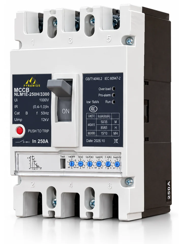
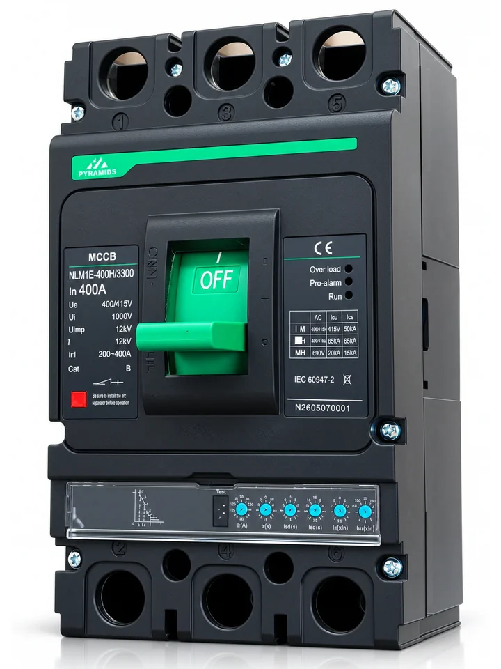
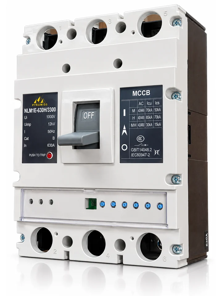
Model No.
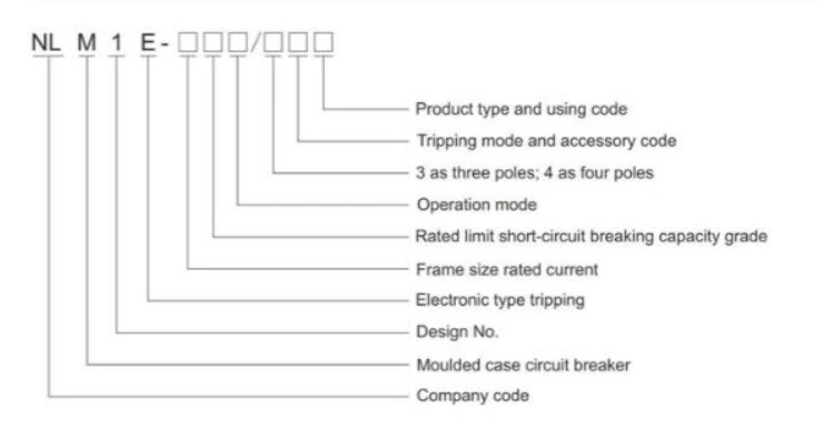
Ratings by frame size
Main Technical Specification
Quick selection
Swipe the table sideways to see all columns.
| Model | Frame Inm (A) | Rated current In (A) | Icu M / H (kA) |
|---|---|---|---|
| NLM1E-125 | 125 | – | 50 / 65 |
| NLM1E-250 | 250 | – | 50 / 85 |
| NLM1E-400 | 400 | 400 | 65 / 85 |
| NLM1E-630/800 | 630 / 800 | 630, 800 | 70 / 85 |
| NLM1E-1250 | 1250 | 800, 1000, 1250 | 80 (M only) |
Summary of the full table below. A dash (–) means the catalogue gives no value. M and H are the breaking capacity classes.
Swipe the table sideways to see all columns.
| Model | NLM1E-125 | NLM1E-250 | NLM1E-400 | NLM1E-630/800 | NLM1E-1250 | ||||
|---|---|---|---|---|---|---|---|---|---|
| Frame current Inm(A) | 125 | 250 | 400 | 630/800 | 1250 | ||||
| Breaking capacity class | M | H | M | H | M | H | M | H | M |
| Rated current In(A) | 400 | 630、800 | 800、1000、1250 | ||||||
| Pole | 3、4 | 3 | 3、4 | 3 | 3、4 | 3 | 3、4 | 3 | 3 |
| Rated voltage Ue(V) | AC400/690 | ||||||||
| Rated insulated voltage Ui(V) | 1000 | ||||||||
| Rated impulse withstand voltage Uimp(V) | 12000 | ||||||||
| Rated limited short-circuit breaking capacity Icu(kA) | 50 | 65 | 50 | 85 | 65 | 85 | 70 | 85 | 80 |
| Rated working short-circuit breaking capacity Ics(kA) | 35 | 50 | 35 | 65 | 50 | 65 | 50 | 70 | 50 |
| Rated short time withstand current Icw 0.5S(kA) | -- | -- | 5 | 10 | 15/1s | ||||
| Using category | A | B | B | B | B | ||||
| Arc distance(mm) | ≤50 | ≤50 | ≤100 | ≤100 | ≤100 | ||||
| Operation performancePower on(Times) | 1500 | 1000 | 1000 | 500 | 500 | ||||
| Operation performancePower off(Times) | 8500 | 7000 | 4000 | 3000 | 3000 | ||||
Wiring types and accessories
Swipe the table sideways to see all columns.
| Wiring type and accessories | NLM1E-125 | NLM1E-250 | NLM1E-400 | NLM1E-630/800 | NLM1E-1250 |
|---|---|---|---|---|---|
| Front plate wiring | ○ | ○ | ○ | ○ | ○ |
| Back plate wiring | ○ | ○ | ○ | ○ | |
| Plug-in wiring | ○ | ○ | ○ | ○ | |
| Drawer wiring | ○ | ○ | ○ | ||
| Under voltage release | ○ | ○ | ○ | ○ | ○ |
| Shunt release | ○ | ○ | ○ | ○ | ○ |
| Auxiliary contact | ○ | ○ | ○ | ○ | ○ |
| Alarm contact | ○ | ○ | ○ | ○ | ○ |
| Motor operation mechanism | ○ | ○ | ○ | ○ | ○ |
| Manual operation mechanism | ○ | ○ | ○ | ○ | ○ |
| Hand test device | ○ | ○ | ○ | ○ | |
| Intelligent control module | ○ | ○ | ○ | ○ | ○ |
| Test power module | ○ | ○ | ○ | ○ | ○ |
| LCD display module | ○ | ○ | ○ | ○ | ○ |
○ marks what is listed for that frame size; a blank cell means not listed.
Electronic release
Release characteristic
1.Electronic release characteristic
Breaker is installed current sensor with effective value sampling . MCCB is with the functions of overload long delay inverse time, short-circuit short delay inverse time, short-circuit short delay definite time, short-circuit instantaneous action and so on, the user can set the protection characteristic they need.
Release characteristic as picture 1
2. Overload long delay inverse time protection action characteristic as form 3
3. Short-circuit short delay protection action characteristic as form 4
4. short-circuit instantaneous protection action characteristic as form 5
Swipe the table sideways to see all columns.
| Current | Action time (S) | ||||||
|---|---|---|---|---|---|---|---|
| Distribution Type | 1.05IR | > 2h no tripping | |||||
| 1.3IR | ≤1h tripping | ||||||
| 2IR | Action time TR | 12 | 60 | 80 | 100 | 150 | |
| Setting time tR | 12 | 60 | 80 | 100 | 150 | ||
| Motor protection Type | 1.05IR | > 2h no tripping | |||||
| 1.2IR | ≤1h tripping | ||||||
| 1.5IR | Action time TR | 21.3 | 107 | 142 | 178 | 267 | |
| 2 IR | Setting time tR | 12 | 60 | 80 | 100 | 150 | |
| 7.2IR | Action time TR | 0.93 | 4.63 | 6.17 | 7.72 | 11.6 | |
| Release class | / | 10A | 10 | 20 | 30 | ||
Swipe the table sideways to see all columns.
| short delay action characteristic | Current Isd | Action time(S) | ||||||||||||||||||
|---|---|---|---|---|---|---|---|---|---|---|---|---|---|---|---|---|---|---|---|---|
| ≤0.9 Isd | No tripping | |||||||||||||||||||
| ≥1.1 Isd | tripping | |||||||||||||||||||
| short delay protection | inverse time protection | Isd ≤I < 1.5 Isd | I²TR=(1.5 Isd)² t5d | |||||||||||||||||
| definite time protection | 1.5 Isd≤I < Ii |
| ||||||||||||||||||
| Accuracy | Inverse time action time | |||||||||||||||||||
| Action characteristic | Current | Action time(S) |
|---|---|---|
| ≤0.85Ii | No tripping | |
| ≥1.15Ii | Tripping | |
Contacts, releases and power
Accessories and Power Consumption
| Classify | Frame rated current Inm(A) | Conventional thermal current Ith(A) | Rated working current | |
|---|---|---|---|---|
| AC400V | DC220V | |||
| Auxiliary contact | Inm≤ 400 | 3 | 0.3 | 0.15 |
| Inm≥ 400 | 3 | 0.4 | 0.15 | |
| Alarm contact | 100≤ Inm≤ 800 | 3 | 0.3 | 0.15 |
Rated control power voltage (Us) and rated operating voltage (Ue) of control circuit release and the motor mechanism to see form 7
| Type | Rated voltage(V) | |||
|---|---|---|---|---|
| AC 50HZ | DC | |||
| Release | Shunt release | Us | 220 380 | 110 220 |
| Under voltage release | Ue | 220 380 | - - | |
| Motor mechanism | Us | 220 380 | 110 220 | |
Release unit technical parameter
- It should reliably break the circuit breaker, when the applied voltage of shunt release is between 70% and 100% of the rated control power voltage.
- The under-voltage release can reliably break the circuit breaker when the power voltage reduces to the 70%~35% of the under-voltage's rated operating voltage; The under-voltage release can prevent the circuit breaker close when the power voltage is lower than 35% of the under-voltage's rated operating voltage; The under-voltage release can ensure the circuit breaker can reliably close when the power voltage is higher than 85% of the under-voltage's rated operating voltage.
- When the motor mechanism is at rated frequency, and the power voltage is between 85%~110%, the circuit breaker can be reliably closed.
The power consumption and derating coefficient
1.power consumption as form 8
| Model | Current (A) | Three phase total power consumption (VA) | |
|---|---|---|---|
| Front/back plate wiring | Plug-in wiring | ||
| NLM1E-125 | 100 | 35 | 40 |
| NLM1E-250 | 225 | 62 | 70 |
| NLM1E-400 | 400 | 115 | 125 |
| NLM1E-800 | 800 | 262 | 294 |
Outline and mounting size (mm)
Appearance and installation dimension
Choose a wiring type, then tap a drawing to enlarge it.
Front panel wiring
Installation Dimensions for NLM1E-125, 250, 400, 630, 800, Front Panel Connection
| Model Specification | NLM1E-125 | NLM1E-250 | NLM1E-400 | NLM1E-630 | NLM1E-800 | NLM1E-1250 | |
|---|---|---|---|---|---|---|---|
| Mounting Dim. (mm) | a/a1 | 30 | 35 | 44/50 | 70 | 70 | 70 |
| b | 129 | 126 | 194 | 243 | 243 | 243 | |
| Φd | Φ4.5 | Φ4.5 | Φ7 | Φ7 | Φ7 | Φ7 | |
Swipe the table sideways to see all columns.
| Model Specification | Poles | Overall Dimensions (mm) | |||||||||||||
|---|---|---|---|---|---|---|---|---|---|---|---|---|---|---|---|
| W | W1 | W2 | W3 | L | L1 | L2 | L3 | H | H1 | H2 | H3/H4 | AM | Y | ||
| NLM1E-125M/H | 3P | 92 | 30 | 16 | 28 | 150 | 132 | 102 | 54 | 112 | 82 | 82 | 28 | M8 | 50 |
| 4P | 122 | ||||||||||||||
| NLM1E-250M/H | 3P | 107 | 35 | 22 | 27 | 165 | 144 | 102 | 54 | 112 | 94 | 85 | 23 | M8 | 60 |
| 4P | 142 | ||||||||||||||
| NLM1E-400M/H (630 Up-ratNL 630) | 3P | 150 | 48 | 30 | 60 | 257 | 224 | 174 | 82 | 151 | 112 | 98 | 37/39 | M10 | 110 |
| 4P | 198 | ||||||||||||||
| NLM1E-630M/H (630 Standard 630) | 3P | 182 | 58 | 40 | 66 | 270 | 234 | 185 | 82 | 158 | 116 | 105 | 42/39 | M12 | 110 |
| 4P | / | ||||||||||||||
| NLM1E-800M/H (800 630 800 Frame 630) | 3P | 210 | 70 | 44 | 66 | 280 | 243 | 202 | 75 | 158 | 119 | 104 | 44/41 | M12 | 110 |
| 4P | 280 | ||||||||||||||
| NLM1E-1250 | 3P | 210 | 70 | 44 | 66 | 280 | 243 | 202 | 75 | 158 | 119 | 104 | 44/41 | M12 | 110 |
Notes:1. Dimension W2 is the recommendNL maximum width for customer wiring.2. AM denotes the terminal screw for customer connection.3. It is recommendNL that 4-pole products be mountNL using the four holes of (a+a1).4. The busbar and overall dimensions of NLM1E-1250 may adopt the overall and mounting dimensions of NLM1-1600.
Plug-in rear connection
Outline, Mounting & Cutout Drawing for NLM1E Electronic MCCB, Plug-in Rear Connection
Swipe the table sideways to see all columns.
| Model | NLM1E-125 | NLM1E-250 | NLM1E-400 400&400Up-ratNL to 630A | NLM1E-630 NLM1E-630 (Standard) | NLM1E-630/800 | |||||
|---|---|---|---|---|---|---|---|---|---|---|
| Poles | 3P | 4P | 3P | 4P | 3P | 4P | 3P | 4P | 3P | 4P |
| Overall Dimensions (mm) | ||||||||||
| W | 91 | 125 | 107 | 145 | 149 | 200 | 182 | / | 210 | 280 |
| H | 50 | 50 | 60 | 60 | 87 | |||||
| H1 | 33 | 33 | 38 | 40 | 60 | |||||
| H2 | 32 | 37 | 46 | 50 | 22 | |||||
| H3 | 17 | 18 | 21 | 28 | / | |||||
| H4 | 4 | 5.5 | 8 | 11 | / | |||||
| L | 168 | 186 | 280 | 300 | 305 | |||||
| L1 | 92 | 94 | 170 | 170 | 178 | |||||
| L2 | 132 | 145 | 224 | 234 | 242 | |||||
| AM | M6 | M6 | M8 | M8 | M10 | |||||
| BM | M8 | M8 | M12 | M12 | M14 | |||||
| Mounting Dim. | ||||||||||
| a | 60 | 90 | 70 | 105 | 60 | 108 | 100 | / | 90 | 162 |
| b | 56 | 54 | 129 | 123 | 144 | |||||
| 4×Φd | Φ7 | Φ7 | Φ9 | Φ9 | Φ12 | |||||
| W1 | 101 | 135 | 117 | 155 | 159 | 210 | 192 | / | 220 | 290 |
| L3 | 82 | 84 | 160 | 160 | 168 | |||||
| L4 | 178 | 196 | 290 | 310 | 315 | |||||
NLM1E-1250
Pictured11 NLM1E-1250 Front plate wiring and installation size
Compliance and conditions
Standards and Working Conditions
StandaNLs
- GB/T 14048.1 Low-voltage switchgear and controlgear — Part 1: General rules
- GB/T 14048.2 Low-voltage switchgear and controlgear — Part 2: Circuit-breakers
- GB/T 14048.4 Low-voltage switchgear and controlgear — Part 4-1: Contactors and motor-starters — Electromechanical contactors and motor-starters (including motor protective devices)
- GB/T 14048.5 Low-voltage switchgear and controlgear — Part 5-1: Control circuit devices and switching elements — Electromechanical control circuit devices
- IEC 60947-1:2020 Low-voltage switchgear and controlgear — Part 1: General rules
Normal working condition and Installation environment
- Altitude of installation site: not exceeding 2000 m;
- Ambient air temperature shall not exceed +50°C, and the 24-hour average temperature shall not exceed +50°C. The lower limit of ambient air temperature is -5°C;
- At the maximum temperature of +50°C, the relative humidity of air shall not exceed 50%. Higher relative humidity is permitted at lower temperatures, e.g. up to 90% at 20°C. Special measures shall be taken against condensation occasionally formed on the product due to temperature variation;
- Pollution degree: 3;
- Installation category for the main circuit of the circuit-breaker: Category III; installation category for auxiliary and control circuits not connected to the main circuit: Category II;
- Selectivity type: A or B.
Get the full NLM1E catalog
Download the PDF catalog, or send us your frame size, rated current, pole number and wiring type and our team will prepare a quotation.
Call us on 01001539094 or 01012235710, or message us on WhatsApp.